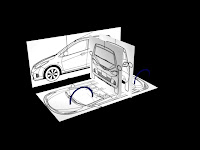
Step 1-3
1. Create a plane in the Top view. In this scene, I use 54x23 for my rectangle dimension. Then this bitmap (see pic below) is assigned to the plane using Material Editor. Then I called it Ref Plane.
1. Create a plane in the Top view. In this scene, I use 54x23 for my rectangle dimension. Then this bitmap (see pic below) is assigned to the plane using Material Editor. Then I called it Ref Plane.
2. Create another plane across the ref plane in step 1 with length and width segments are sets to 1. Convert the plane you just created to Editable Poly and assigned it with green color. Create a number of lines as much as the ref plane has. This is to make tyre surface edge soon. Use your own creativity to design the tyre surface. The more complicated you did, the more realistic surface you can get. One thing you should know, don’t ever rescale the plane. Just move the edge in y-axis.
3. Extrude polygons you have selected. In this scene, I choose 4 polygons and extrude it about 6.0 of extrusion height.
Step 4-6
4. Detail out your plain with a number of edges. Again, use your creativity.
5. In this step number 5, I have selected a number of polygons and delete them. This to make sure each of the planes will smoothly attach each other when we copy them later.
6. So that is my single plane. How about you?
4. Detail out your plain with a number of edges. Again, use your creativity.
5. In this step number 5, I have selected a number of polygons and delete them. This to make sure each of the planes will smoothly attach each other when we copy them later.
6. So that is my single plane. How about you?
Step 7
7. While the plane is selected, in the ‘Type of Object’ parameter, choose ‘copy’. In the Array dimension, choose ‘1D’ and key in number 5 for ‘count’. Then go to ‘Tools’ and ‘Array’. Click on the arrow button on the right side of ‘Move’. I use -56. You can use larger number in count but you must set higher y-axis amount. Press preview button to see what happen to your plane. Instead, you can roll the y-axis amount up and down to see the plane direction. All we want to get is to place the planes side by side. After that, click OK. Now you have 5 planes on your viewport.
Step 8-9
8. Now attach all 5 planes. Then turn to vertex selection and select the entire vertex from 5 planes you have just attached.
9. Weld them with 0.1 thresholds and click OK. I repeat step 7-9 two times and this is resulting a long attached plane.
Step 10-12
10. I move the plane pivot and place it to the left most of the plane. Then the pivot adjustment is turn off. After that, with the plane is selected, I place it on x-y-z to 0-0-0. This is to make sure your plane is situated on the baseline or centre of the viewport.
11. While the plane is selected, use symmetry modifier in the modifier list. Choose X for mirror axis and click flip if possible. Refer to photo below.
12. Here comes our plane.
Step 13-14
13. This is the most interesting step. Using Bend modifier, I use -362 for angle and -90 for direction. Choose the axis while you can preview how your plane will look alike. In my viewport, I choose Y axis. Refer to photo below.
14. This is the result.
Step 15-16
15. Then, turn on the vertex selection. Select vertices from the area which both end of the plane were attached. This will turn the plane we bend before to a piece of cylinder. From now, I call this cylinder as a tyre.
16. Move the tyre pivot to center. You can do it by selecting all the vertices and change the axis coordinate to 0-0-0.
Step 17-18
17. From the picture, you can see both side of the tyre edges were selected using border selection method.
18. The selected edges were scaled down using Uniform Scale button. How much you scale down is up to you. Whether you want to have a high profile or low profile tyre, depend on what we need.
Step 19-20
19. I just add some more details on the tyre.
20. Finally, our tyre is finished.
Lets see the finished result which is equipped with UVW Mapping and Bump while rendered in Mental Ray.


