Salam, Hey guys, I am about to change this blog to wordpress. My new weblink will be
http://fridzmax.wordpress.com/
Or click on FridzMAX on the right side bar for quick access to fridzmax.wordpress
Thanks for supporting me and commenting in my posting.
August 11, 2010
July 28, 2010
FridzMax: Some 3d Models of mine
Salam. Just to show how its going on during my modeling session. I am using Autodesk 3ds Max 2009. Let's see some photo.
This is my own design. A c-segment sedan derived from Mazda 6. Borrowing Renault Dezir's wheel arc.
A sport hatch based on VW Scirocco. Also my own creation. The model development was discontinued due to undisclosed factor. Hahahaha
The most hanging project, that is Lotus Evora 20% complete.
Lotus Evora during modeling.
Proton EMAS (Eco Mobility Advanced Solution) during development stage.
Playing with interior lighting setup using Mental Ray renderer. that shower screen, toilet bowl and wash basin were 100% imported from artist-3d.com. The only thing I made is the WAL. Hahaha
Labels:
3d Modeling,
Mental Ray
July 26, 2010
Proton Exora MPV Facelift 2010
Salam. It's been a long time I doesn't have any 3d model to publish. Ok, this time I may show you the Malaysian made MPV. That is Proton Exora with some minor facelift, (copying grill design from somewhere else). I think the grill design is taken from our Proton Wira Special Edition. I am using Audi A1 sport rims for this model. Lets take a look on the model.
Ordinary Proton Exora
The facelift model equipped with front and side fancy skirting.
Proton Exora R3 Lotus Racing Edition.
Equipped with Lotus Green-Yellow theme and Satria Neo Sport Rims..
That's for today. Thanks..
(In Bahasa Malaysia)
Permintaan Bro Animous untuk memperlihatkan Exora diatas dalam 'Edge Face Mode'..Mari kita lihat bersama. (saya bukan pro, biasa2 je)
Ok, gambar-gambar diatas semuanya dihasilkan menggunakan perisian Autodesk 3DS Max. Saya masih lagi menggunakan versi 2009. Tiada Photoshop sama sekali untuk penghasilan gambar diatas. Photoshop dan Illustrator masih lagi digunakan untuk menghasilkan tema Hijau Kuning Lotus Racing (Photoshop) dan blueprint model Exora (illustrator).
Contoh bahagian pintu, front fender, bumper dan tingkap yg tidak di-turbosmooth.
Dah turbosmooth..Nanti saya tunjukkan bagaimana sesuatu edge dpt ditampilkan walaupun kita apply turbosmooth..ok. Tkasih.
June 19, 2010
Honda City 2011; My Impression.
Salam. Hi guys. I am back with the brand new artwork of mine. How do I start this column? Ok, I called this as a B-segment car with C-segment characteristics. Initiated from Hyrax Sketches (refer) http://hyraxsketch.blogspot.com/2010/04/proton-concept-design-idea.html and with some modification, I derived it in different way and try to find my own identity. Btw, thanks to Firdaus Hyrax.
This model actually was derived from multiple car design. There are Proton Emas, Audi TT 2008, Honda Civic FD2 and Hyrax Concept Design. But for this model, I named it as Honda City 2011. Because, I saw Honda City in certain of view. Huhu.
Lets take a look on the model.
The Type R version equipped with Audi R8 Spider sport rim and Mitsubishi Evo X rear spoiler.
Material testing trial render.
Rally Ypres Belgium 2010 Edition. Using Skoda Motorsport body sticker.
Okay, see you again.
Labels:
City Car,
Mental Ray,
Studio Rendering
May 16, 2010
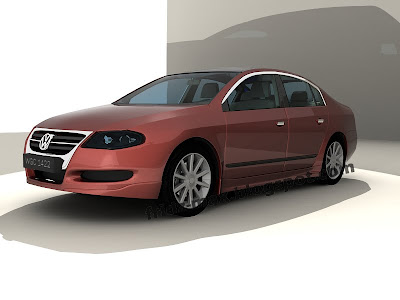
May 2010 VW Passat
VW Passat 2008.

Imagination: VW Passat as a government official enforcement vehicle. Department of Environment Malaysia.

Imagination: VW Passat as a government official enforcement vehicle. Department of Environment Malaysia.
Labels:
Mental Ray,
Studio Rendering
How to Design a Realistic 3D Tyre Model Using 3ds Max
Step 1-3
1. Create a plane in the Top view. In this scene, I use 54x23 for my rectangle dimension. Then this bitmap (see pic below) is assigned to the plane using Material Editor. Then I called it Ref Plane.
1. Create a plane in the Top view. In this scene, I use 54x23 for my rectangle dimension. Then this bitmap (see pic below) is assigned to the plane using Material Editor. Then I called it Ref Plane.
2. Create another plane across the ref plane in step 1 with length and width segments are sets to 1. Convert the plane you just created to Editable Poly and assigned it with green color. Create a number of lines as much as the ref plane has. This is to make tyre surface edge soon. Use your own creativity to design the tyre surface. The more complicated you did, the more realistic surface you can get. One thing you should know, don’t ever rescale the plane. Just move the edge in y-axis.
3. Extrude polygons you have selected. In this scene, I choose 4 polygons and extrude it about 6.0 of extrusion height.
Step 4-6
4. Detail out your plain with a number of edges. Again, use your creativity.
5. In this step number 5, I have selected a number of polygons and delete them. This to make sure each of the planes will smoothly attach each other when we copy them later.
6. So that is my single plane. How about you?
4. Detail out your plain with a number of edges. Again, use your creativity.
5. In this step number 5, I have selected a number of polygons and delete them. This to make sure each of the planes will smoothly attach each other when we copy them later.
6. So that is my single plane. How about you?
Step 7
7. While the plane is selected, in the ‘Type of Object’ parameter, choose ‘copy’. In the Array dimension, choose ‘1D’ and key in number 5 for ‘count’. Then go to ‘Tools’ and ‘Array’. Click on the arrow button on the right side of ‘Move’. I use -56. You can use larger number in count but you must set higher y-axis amount. Press preview button to see what happen to your plane. Instead, you can roll the y-axis amount up and down to see the plane direction. All we want to get is to place the planes side by side. After that, click OK. Now you have 5 planes on your viewport.
Step 8-9
8. Now attach all 5 planes. Then turn to vertex selection and select the entire vertex from 5 planes you have just attached.
9. Weld them with 0.1 thresholds and click OK. I repeat step 7-9 two times and this is resulting a long attached plane.
Step 10-12
10. I move the plane pivot and place it to the left most of the plane. Then the pivot adjustment is turn off. After that, with the plane is selected, I place it on x-y-z to 0-0-0. This is to make sure your plane is situated on the baseline or centre of the viewport.
11. While the plane is selected, use symmetry modifier in the modifier list. Choose X for mirror axis and click flip if possible. Refer to photo below.
12. Here comes our plane.
Step 13-14
13. This is the most interesting step. Using Bend modifier, I use -362 for angle and -90 for direction. Choose the axis while you can preview how your plane will look alike. In my viewport, I choose Y axis. Refer to photo below.
14. This is the result.
Step 15-16
15. Then, turn on the vertex selection. Select vertices from the area which both end of the plane were attached. This will turn the plane we bend before to a piece of cylinder. From now, I call this cylinder as a tyre.
16. Move the tyre pivot to center. You can do it by selecting all the vertices and change the axis coordinate to 0-0-0.
Step 17-18
17. From the picture, you can see both side of the tyre edges were selected using border selection method.
18. The selected edges were scaled down using Uniform Scale button. How much you scale down is up to you. Whether you want to have a high profile or low profile tyre, depend on what we need.
Step 19-20
19. I just add some more details on the tyre.
20. Finally, our tyre is finished.
Lets see the finished result which is equipped with UVW Mapping and Bump while rendered in Mental Ray.
Labels:
Step by Step
April 16, 2010
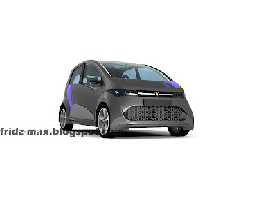
Proton EMAS in Mental Ray
I am still using the Mental Ray renderer on this model. But with a little tweak, I just get what I want. Here are some parameter that's been utilized to get the above photo:
Body color and material:
1) The chrome parts, Matte Finished = Arch and Design (mi)
2) The body color = Car Paint Material (mi) with self design blue chessboard mapping
3) Lower Grill Cover = default color with opacity and bump mapping
Lighting Setup
1) I only use skylight and Scene Environment is turn on (shown in picture below)
2) 1 Target Direct Light with specific angle with Ray Traced Shadows and 0.676 Intensity.
3) and 1 MR Area Omni Light with Ray Traced shadows and 0.4 Intensity
Lets take a look on the light coordination. (picture below)
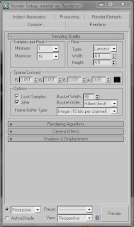
Render Setup
1) On the Mental Ray Render Setup tab, I use Lanczos and min=1 and max=16 Samples per pixel
(Picture shown below)

2) I turn on the Final Gather to Medium preset
3) I also use blank white mapping in the Environment Map
And there is other picture that I want to show off. Thanks

Labels:
City Car,
Mental Ray,
Studio Rendering
Subscribe to:
Posts (Atom)


